

 Current position > Product detail
『Endress and Hauser Ultrasonic Flow Meter Configuration for Process Water』Related information(clamp on meter|electromagnetic meter|venturi meterrotameter|orifice meter|ultrasonic flow meter|mass flow meter|coriolis mass flow meter|coriolis flow meter|magnetic flow meter|magmeter flow meter|magflow flow meter|mag meter flow meter|electromagnetic flow meter|vortex flow meter|turbine flow meter|thermal mass flow meter|thermal flow meter|rotameter flow meter)
 ```html
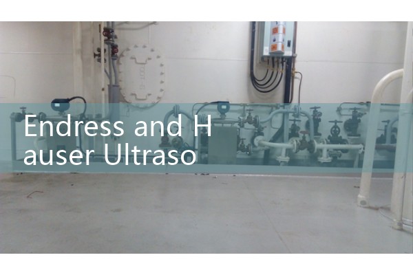
Endress and Hauser Ultrasonic Flow Meter Configuration for Process Water
Quick Answer: Endress+Hauser ultrasonic flow meters for process water usually ship with a default setup that needs site‑specific adjustment. You must verify the sensor type, pipe material, lining, fluid properties, and output scaling. A clamp‑on Proline Prosonic Flow 91W or an inline 93P will deliver ±1 % accuracy once you enter the actual sound velocity of the water and the correct pipe circumference.
Why the Default Configuration Is Not Enough
Most engineers skip this part because the meter shows a flow reading right out of the box. Here is the thing. Process water is not pure water. It can carry traces of glycol, suspended solids, or a few percent of caustic. That changes the speed of sound. When you leave the factory sound velocity setting, you accept a 2 to 4 % deviation you will never notice until the quarterly mass balance. We have seen this on customer sites many times.
Step 1: Enter the Pipe and Liner Data Correctly
On a clamp‑on sensor like the Prosonic Flow W 400, navigate to Setup → Sensor → Pipe Settings. Key in the exact outer diameter in millimetres. Do not round up. A 114.3 mm OD pipe is not DN100; it is 4 inch schedule 40. Set the pipe material from the onboard library: carbon steel, stainless steel 316L, or PVC. If your pipe has a cement lining or a rubber liner, select it. Even a 3 mm rubber liner will shift the transit time by a measurable amount. For inline meters like the Prosonic Flow P 500, you skip this; the manufacturer already knows the flow tube geometry.
Step 2: Define the Fluid Correctly
Do not just select “Water.” Process water often is not pure. In the Fluid Properties menu you can enter the actual concentration of additives. For example, a sugar mill in Thailand uses process water with up to 5 % molasses carryover. A dairy plant in New Zealand has CIP return water with 0.5 % caustic at 70 °C. Both cases need a custom sound velocity. The E+H transmitter stores tables for water‑glycol and water‑NaOH mixtures. If your fluid is not in the library, you can set the sound velocity manually by taking a sample and measuring it with a portable meter, or by doing a linear adjustment against a known volume. The meter will then use this value to compensate the Reynolds number correction.
Step 3: Scale the Analog and Digital Outputs
Process water loops rarely need a 0 to 10 m/s range. Most DN80 to DN200 lines operate between 0.5 and 3 m/s. Set the 4‑20 mA span to a realistic value, say 0 to 150 m³/h for a DN150 line. This gives the PLC a usable resolution. On the HART or Modbus output, map the primary variable to volume flow at actual conditions. Avoid mass flow unless you have a density input from a separate instrument. We configured a paper mill in Indonesia last month where the flow meter was sending 4‑20 mA with a 0‑500 m³/h span on a DN100 pipe that never exceeded 80 m³/h. The control room only saw a tiny flicker of the signal. Once we rescaled to 0‑100 m³/h, the PID loop stabilised within two hours.
Step 4: Run the Quick Setup Wizard Again
After every parameter change, cycle the power or restart the measurement. The Proline transmitter will recalculate the signal‑to‑noise ratio and reacquire the signal. If the meter is clamp‑on, check the coupling gel and the sensor spacing. A 1 mm gap shifts the path length enough to cause a 0.5 % error. Tighten the mounting straps to the torque printed on the sensor label. Then look at t
When to Switch to an Alternative Meter
Sometimes the pipe condition makes an E+H clamp‑on meter difficult to justify. Heavily corroded pipes with internal scaling reduce the signal so much that even a high‑power sensor fails. In such cases you might need an insertion ultrasonic or an electromagnetic flow meter. Silver Instruments supplies a full‑bore magmeter in DN15 to DN2000 with PTFE or hard rubber liners that works on dirty process water with conductivity down to 5 µS/cm. Our clamp‑on ultrasonic meter uses a similar transit‑time principle and ships with a dedicated tablet for coupling checks. It costs less than half the typical E+H model and supports Modbus RTU, 4‑20 mA HART, and pulse output. We have shipped these to water treatment plants in Nigeria, cooling tower OEMs in Mexico, and a desalination plant in Oman.
Common Troubleshooting After Configuration
If the meter shows zero flow but the pump is running, check the signal diagnostic menu. A low signal strength normally means air bubbles. A fluctuating sound velocity above 1550 m/s can indicate a pipe that is not completely full. Reduce the damping to 3 seconds for control loops and to 10 seconds for totalizers. Do not set it to 1 second; that makes the output noisy. Another trap is the empty pipe detection threshold. On vertical pipes you may need to increase it to 2.0 m/s. Ask our engineers for a remote dial‑in if needed.
FAQ
Can I use an E+H Prosonic Flow on a DN25 process water line?
Yes, but you need the small‑pipe sensor version (Prosonic Flow W 400, sensor size S). The minimum recommended inner diameter is 15 mm. For smaller lines consider an inline Coriolis meter like the Silver Instruments SICOR series, which reads mass flow directly down to DN01.
What is the typical sound velocity of process water I should enter?
Pure water at 25 °C is 1497 m/s. Process water with 1 % NaCl is about 1510 m/s. If your water temperature is above 40 °C, the value drops below 1490 m/s. Always measure a sample when a reference table is not available.
Why does my E+H meter show negative flow?
The flow direction arrow on the sensor is mounted opposite to the actual liquid movement. Go to Setup → Sensor → Installation Direction and toggle the sign, or rotate the sensor pair by 180 degrees.
Does Silver Instruments offer a direct replacement for the E+H Prosonic Flow 91W?
Yes. Our model SUF-300 clamp‑on ultrasonic meter has the same mounting rail and compatible output codings. Send us your pipe OD, material, wall thickness, and fluid temperature; we will recommend the exact part number. Email [email protected] or call +86-25-68650347.
Can I get a price quote for a process water meter with 4‑20 mA HART and IP68?
Absolutely. Tell us the required flow range, pipe size (DN), pressure in bar, temperature in °C, and your preferred cable length. We reply within 4 hours on business days. Reach us at [email protected] or by WhatsApp at +86-25-52155837.
Contact Silver Automation Instruments
Email: [email protected]
Tel: +86-25-68650347
Whatsapp: +86-25-52155837
WeChat: +86 15365082610
Web: flow-meter.com.au